Reducing Sidelobes of SRF10
Article
contributed by Harold Carey
hrcarey@comcast.net
The price to pay for the SRF10’s tiny transducers is that the system is now very sensitive to objects way off boresight (boresight is the angle where the sonar is aimed, that is, straight ahead). In fact the sonar will respond continuously to the ground if aimed horizontally and mounted at a height of 3 feet or less. The published curves show the response pattern in dB, but what is more practical for my purposes is a plot of the distance an object will be detected vs. its angle from boresight. The SRF10 responds to a narrow object 30 inches away at an angle of 60 degrees below boresight, even with drastically reduced gain! This is certainly a false alarm for most applications (including mine).
Reducing the gain cuts down the sidelobes somewhat, but not enough.
The pattern up and down (relative to the picture in the book – looking at the component side with wires on left) is not symmetrical. The sonar is much more sensitive to objects below boresight. So if you are mounting your sonar vertically (not side-by-side), mount it up-side-down. And in any case, aim the sensor UP about 30 degrees or more to avoid the ground. Probably the mounting supplied can be bent.
I did some experiments to try to reduce the sensitivity off
boresight. I first installed a
paper tube around both aluminum cans on the sensor.
I tried lengths of 0.8” and 0.5” (measured from the PC board) with
very similar results. I also tried
3/8”ID shrink tubing (without shrinking it) with similar results.
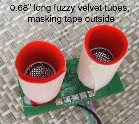
But I also tried fuzzy velvet ribbon, in 2 lengths, with dramatic
results.
These extensions form a tube a couple of wavelengths
(0.339”=8.6mm) long from the transducer, so there is some combination of
open-tube resonance, diffraction, absorption, and collimation happening.
But it seems to be mostly absorption, because the fuzzy ribbon works much
better. In every case, the
sensitivity off boresight is reduced markedly.
My experiment setup was to tape the sensor (aimed
horizontally, with transducers side-by-side) onto a horizontal turntable that
could rotate in azimuth. The
turntable was mounted 5’ above the ground to avoid ground effects.
I worked outside so there would be no interference from room reflections.
I used a paper template to measure the rotation angle every 10 degrees
(you could print the template below). I
laid out a tape measure on the ground, with zero directly under the sonar.
The target was a long ½”-diameter pole held vertically (using a wider
target would be hard to determine its azimuth).
I rotated the sensor to each 10 degree angle, moved the pole along the
tape measure from distant to closer, and recorded the distance where is sonar
responded. I also checked to be sure that there was no dead spot at that
angle. The sonar is operated by a
PIC16F870, with the gain reduced to 100 (setting of 6 in the register, which
just barely detects the target at 53”), and max range reduced to 55”
(setting of 33 in the register). My
results as follows:
You might want to experiment with different lengths of
tube, to see if sidelobes can be reduced further.
Maybe Velcro thicker fuzz or upholstery velvet would be a better
absorber. Maybe a flare like a
trombone would be better. Maybe a
long tube with a slight taper would not affect the center sensitivity, but still
kill off-axis sidelobes. Maybe just
a horizontal flat surface would absorb the ground clutter.